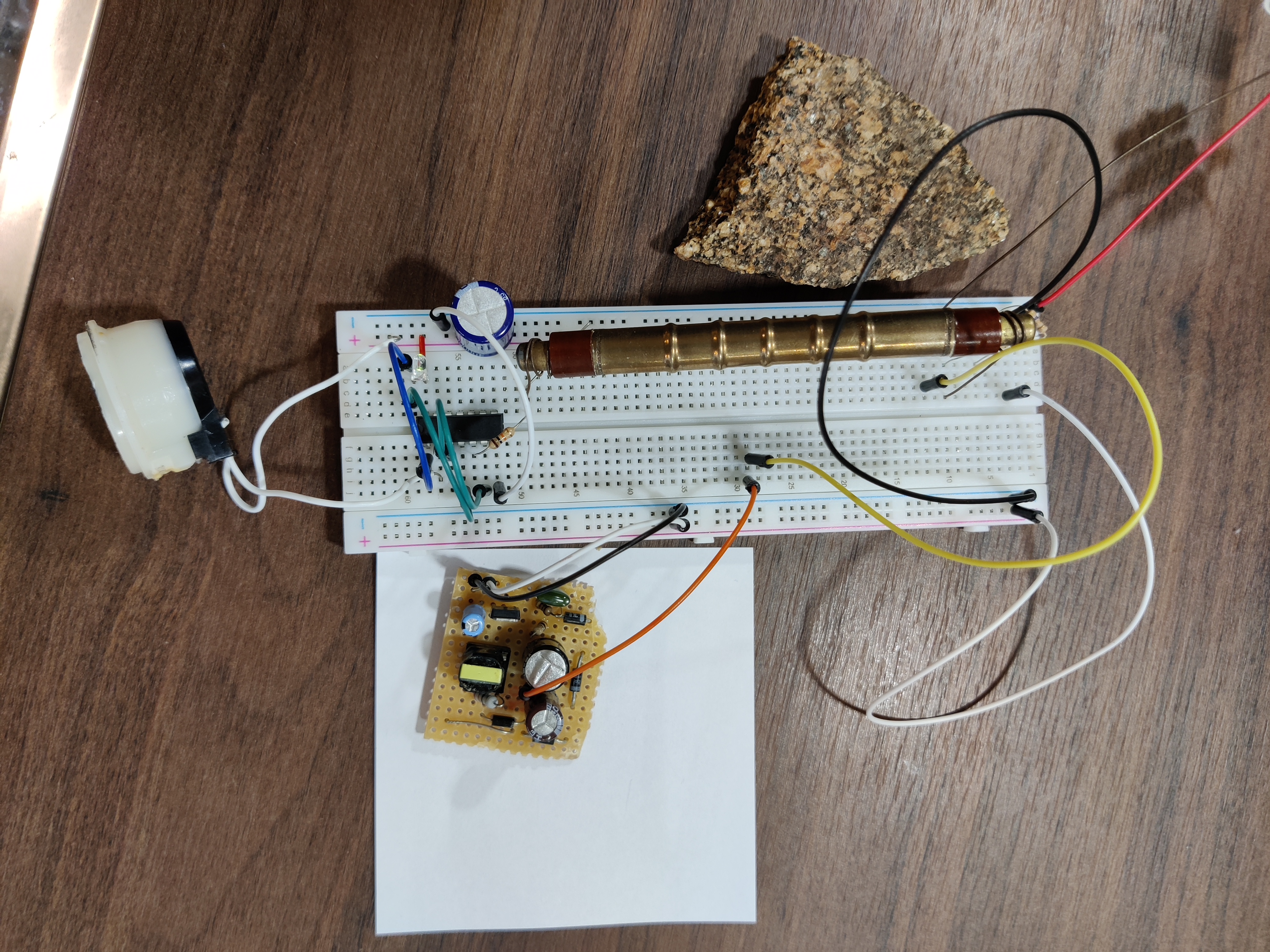
Geiger Counter - a Proof of Concept
Within all of the projects I did and do, there are few finished. This one comes pretty close. This project was pretty influential for me because it sparked a lot of different ideas and projects I do nowadays. The idea was simple, just build a Geiger Counter with off the shelf components and call it done. People in the 1930s were building these things, so how hard could it be?
Motivation
Within physics at german schools, radiation is a standard topic and routinely dealt with over the course of a quarter year. I was about 15 when I learnt about this topic. Being way to practical of a learner for the german scholar system, I decided to additionally research this topic (as per usual for me). Gaining a rising interest in electronics at this point in time, I decided to build my own Geiger counter to see if I could do it and to be able to work with radioactive stuff (somewhat) safely in the future. The circuit seemed simple enough for me to do it.
Safety
As with all projects not everyone attempts, there are reasons for that. While this is also way to expensive in time and money and useless for the average Joe, there is a third reason that applies here. Geiger counters (and electronics in general) as well as radiation have the possibility to kill you. With electricity, it usually also hurts the whole time your dieing; even if you don't die via say a shock it is still going to hurt really bad. I possess electrical training and execute propper safety precautions, even if it does not seem this way. You do not want to play around with high voltage; treat it like a wild animal that can easily come around to bite you in the back. You also do not want to play around with bare circuits, as some components like capacitors still hold charge / voltage (and can kill you) even if the electricity source is disconnected.
The first Attempt
Geiger counters work through specific tubes. A quick google search pointed towards the american M4011/J305 tube, which is readily available online. I decided to buy one and only looked at the datasheet after it arrived.
"Operating voltage 380V-450V." Now I had the major problem of somehow getting high voltage into a small, delicate measuring device. I briefly considered using a 1:2 transformer to stepup the 220V AC from the grid to 440V and just using that, but ultimately decided against that. Judging by my scripts, my reasoning was that I wanted it to be portable. Safety concerns where not my main issue; as you can tell I was young and dumb back then.
Researching into how to get high voltage with a simple circuit, I discovered the so-called "step-up" boost circuits. The principle of why these work was know to me as that's how some ignition systems on gas engines work. I decided to build this circuit using scrap components I had laying around, like a 96VA Myrra transformer I used as coil. At first I tried to build this circuit using a RFT tube as the exciter switch and a 12V alkaline battery as power source. As with all RFT things, this didn't work for a variety of reasons. I then started to experiment with a MOSFET as switch, which didn't work either. It also didn't help that I blew the MOSFET up by accidentally switching Base and Emitter. After putting this project on hold for about a week, I finally got a puny 300V out of the coil utilising a Darlington FET and two batteries. This was not enough, so I looked into voltage multipliers. I added a capacitor-diode ladder to the coil with components I got from a fluorescent lightbulbs igniter circuit. This way I ultimately got the 420V I needed out of the coil. The input voltage only dropped from 24V to 8V while running this circuit, so I called this a highly-efficient and perfect solution to my problem. I then tried to get the classic clicking sound to happen with the parts I had. While trying to mount my tube using custom clamps, I put too much axial torque on the tube I had and ended up braking the thin glass tube. This was when I put the project on hold for another month to focus on exams I had coming up.
Toasting Breadboards
After consulting my physics teacher (and ironically only making mistakes in the radiation detection part of my physics test), I picked the project back up again. My specified goal for this project was now to reach the stage specified later on this page as a proof of concept. Until now, I hadn't even thought about how to electronically count the pulses of the tube and interpret the result. Googling around for a solution, I came across a webpage that made the build way, way easier.
Giangrandi
A swiss electrical engineer by the name of Iacopo Giangrandi has a similar homepage to mine where he mainly talks about the different side projects he did over the years. His site can be accessed at giangrandi.ch. The projects he talks about include Mechanics, Optics, Software and (mainly) Electronics. In 2017, he also wrote an article on building a twin-tube Geiger counter. This article dives a bit deeper into the design considerations he took and I cannot overstate how easy that knowledge made it for me to build my own counter.
Design changes
Giangrandi came up with an unique solution to the problem of generating high voltage. He modified the circuit responsible for creating the flash in a disposable camera in order to create the 400V he needed to run his tubes.
Giangrandi went with two soviet-era SBM-20 tubes which are superior to my choice of tube: They 1. are made out of metal and do not snap easily under axial stress, 2. are even cheaper and easier to source in Europe and 3. have generally better operating conditions.
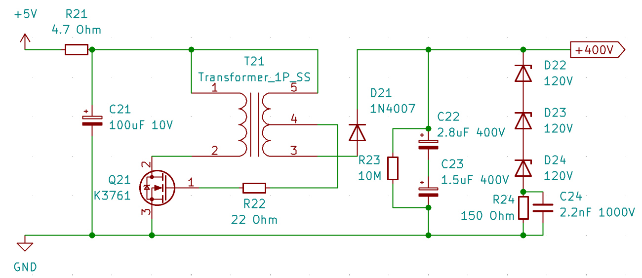
After picking up SBM-20 tubes as well as a disposable camera I went to work designing a high voltage generator. The design decisions Giangrandi made are insanely smart and stuff I generally wouldn't have come up with. The idea of repurposing the flash transformer of a camera to generate the high voltage seems as hacky as something people living in the GDR or Cuba would have (and have) done yet so simple (why reinvent the wheel?), it's just ingenious. Utilising the lessons learned from my previous attempts and Giangrandis website, I got the circuit visible below working. After a lot of trial and error, I settled on the configuration visible below.
Specific modifications
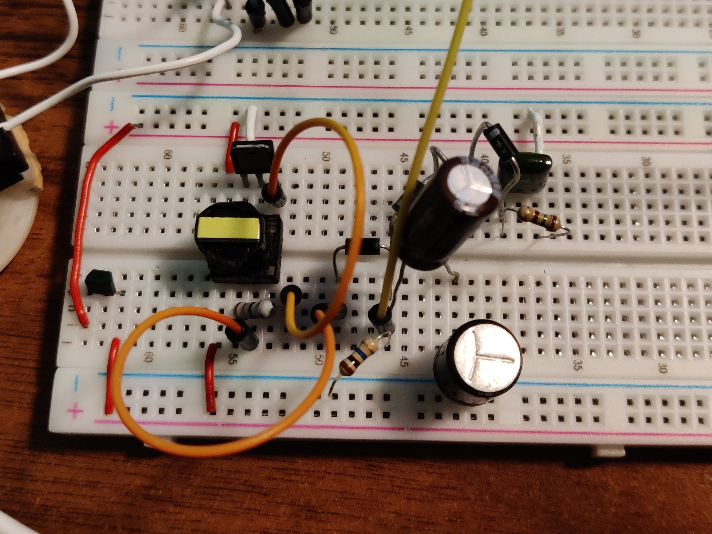
The high voltage module was built on breadboards and was inherently dangerous. It started more than one small fire, shocked me a few times and generally sketched out anyone knowing anything about electronics.
Also, the practical limit to breadboards is around 650V with my conditions. Even before arcing out, the leakage current is high enough to overstress your circuit and eventually blow up your transistor. At this stage I had way to much fun just toasting the bread part out of the breadboards.
(Careful, nerdtalk incoming:)
Compared to Giangrandis design I took some design liberties. I added a series resistor (R21) as I found it to drastically increase safety and component longevity in the event of say a short on the HV rail. The 4.7 Ohm value was determined via Ohms law using manufacturer data for maximum transistor throughput and experimentally verified (yes, this means also shorting 400V and nice orange sparks).
I ended up with an even more rugged transistor, the IRFU 310. This is a somewhat old Power MOSFET which is more than up to the task. I strongly believe in MOSFET supremacy and mainly chose this one because I was fed up with blown transistors and stumbled upon this in the junk bin.
Because of the resistor R21, my feedback resistor R22 necessarily has to be lower as well. It is almost at the value found in the cameras flash module with just 22 Ohm.
Because I did not have a single cap that both could go up to the 600V or so this generator puts out unclamped and still had enough capacity for me to use this generator also for other HV-related projects, I went with two dissimilar series electrolytic caps from the junk pile. They look jank, but work just fine.
My clamping setup is also different in that the Zeners stretch to 360V and the coupled capacitor-resistor pair do the last 40V with smoothing and debouncing (if you can call it that). Just leaving out the capacitor meant spikes of discharge going into the ground rail. This both made for inconsistent output voltage and a fried Arduino I used as insulated 5V power source.
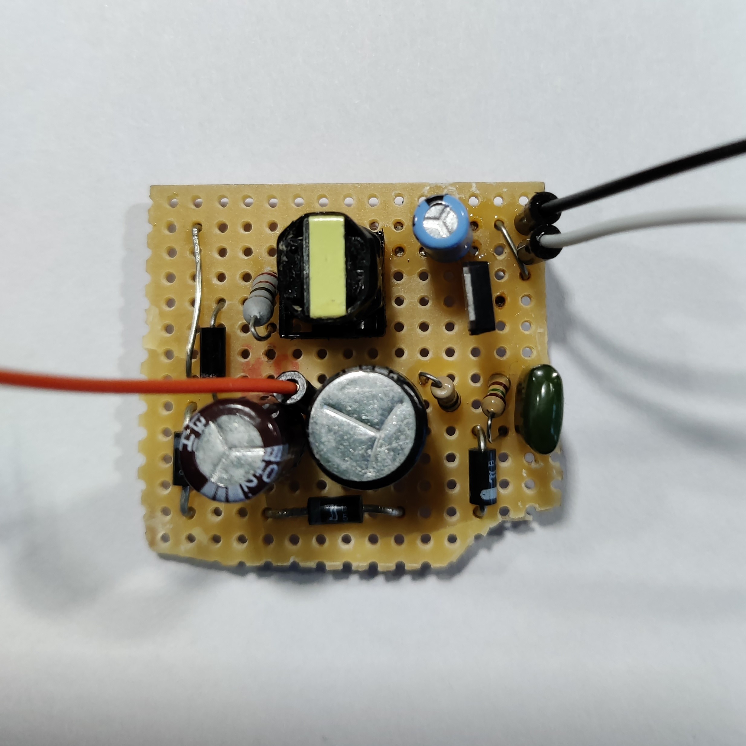
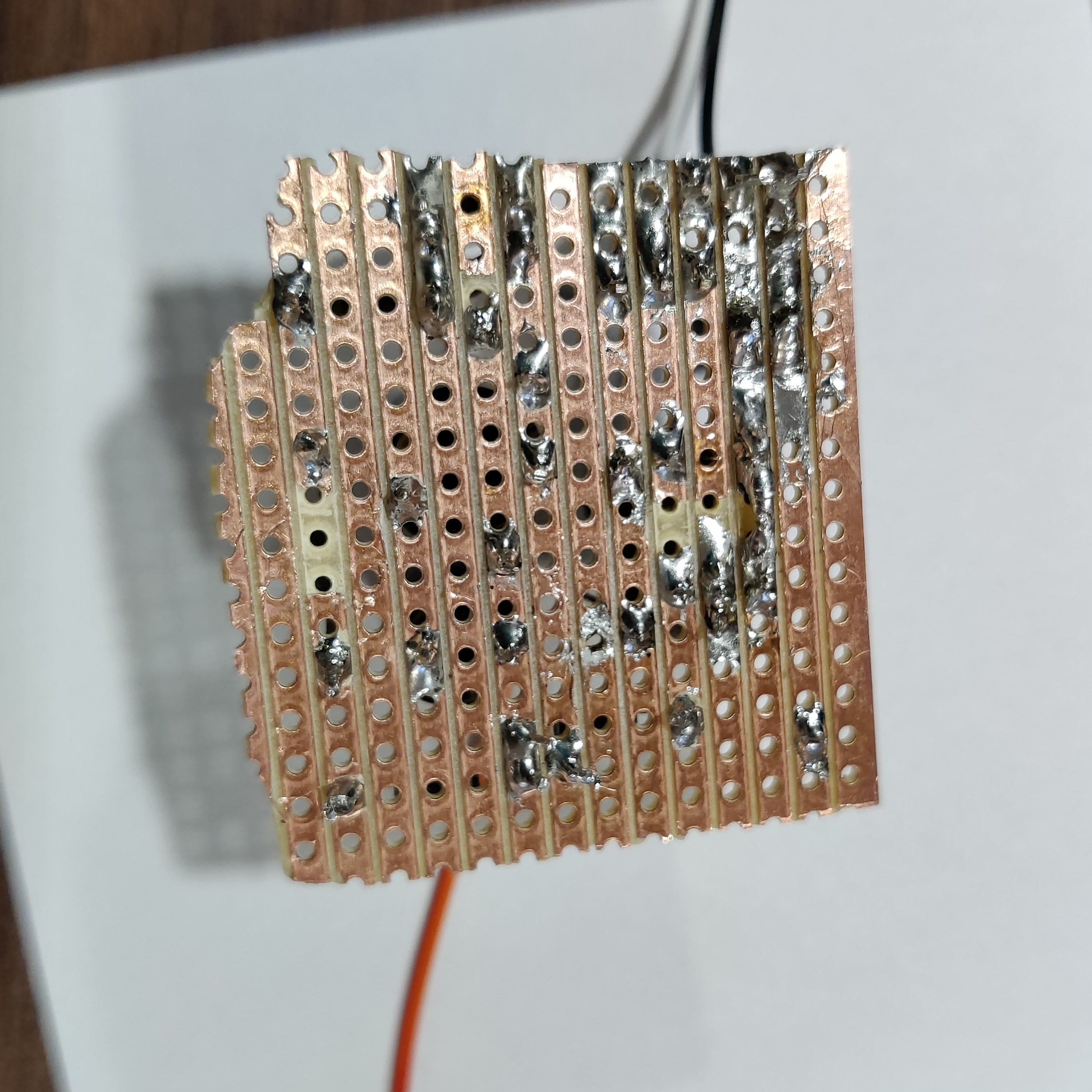
Anyways, I built it out on perfboard eventually and then had a relatively compact and safe HV generator with 5V in and fixed 400V out.
Results
The Geiger counter was finally working. This configuration as of half a year after starting the project was more a Geiger "clicker" than actually a counter. This however worked as a proof of concept, that in fact anyone interested and devoted (=crazy) enough can get something like this working. Comparing this counter to a Geiger counter my school had for educational purposes, it worked just fine. Manually counting and then calculating the activity on a known Strontium sample yielded results within the margin of statistical error, given that the sensitivity on the SBM-20 is lower than on the commercial beta tube.
This project sparked my prolonged interest in electronics and ultimately taught me a lot about electronic principles. The most important takeaways were probably in the realm of safety and design principles. I learned ultimately that there is no such thing as a fully predictable circuit; circuit design always has an element of dark magic. Also, if theory and praxis clash, praxis always wins (theoretically a given resistance should be sufficient, in praxis HV just shorts between the rails and blows up your transistors).
This project also introduced me to Giangrandi and his amazing website. A lot of the knowledge I gained in doing projects is in some way related to his website, especially in the realm of electronics.
There will also be a part two of the project with the instrument in its current state. It will actually count and show radiation numbers by then.
